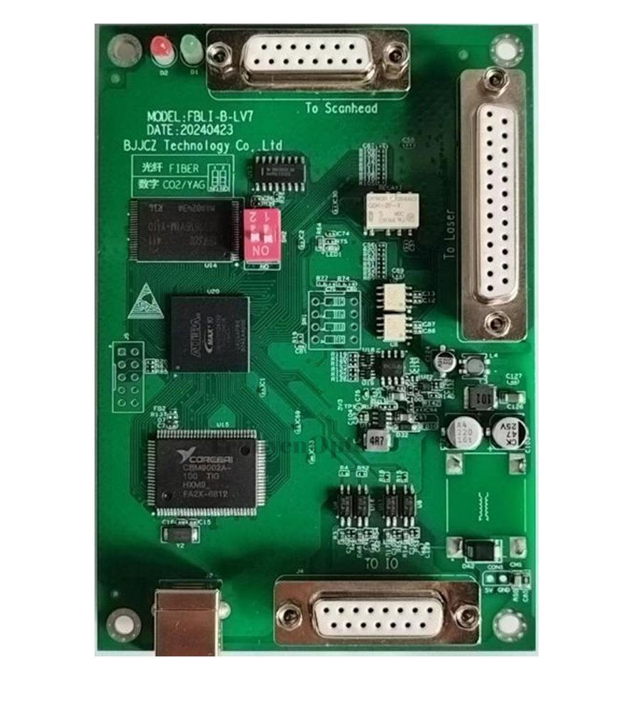
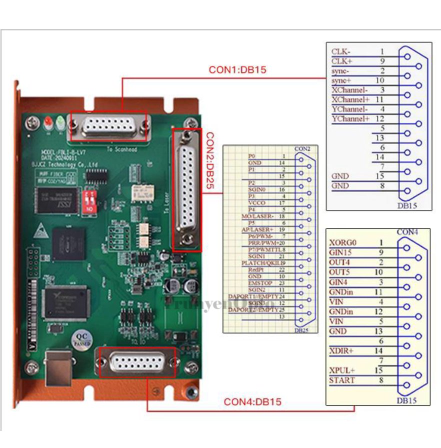
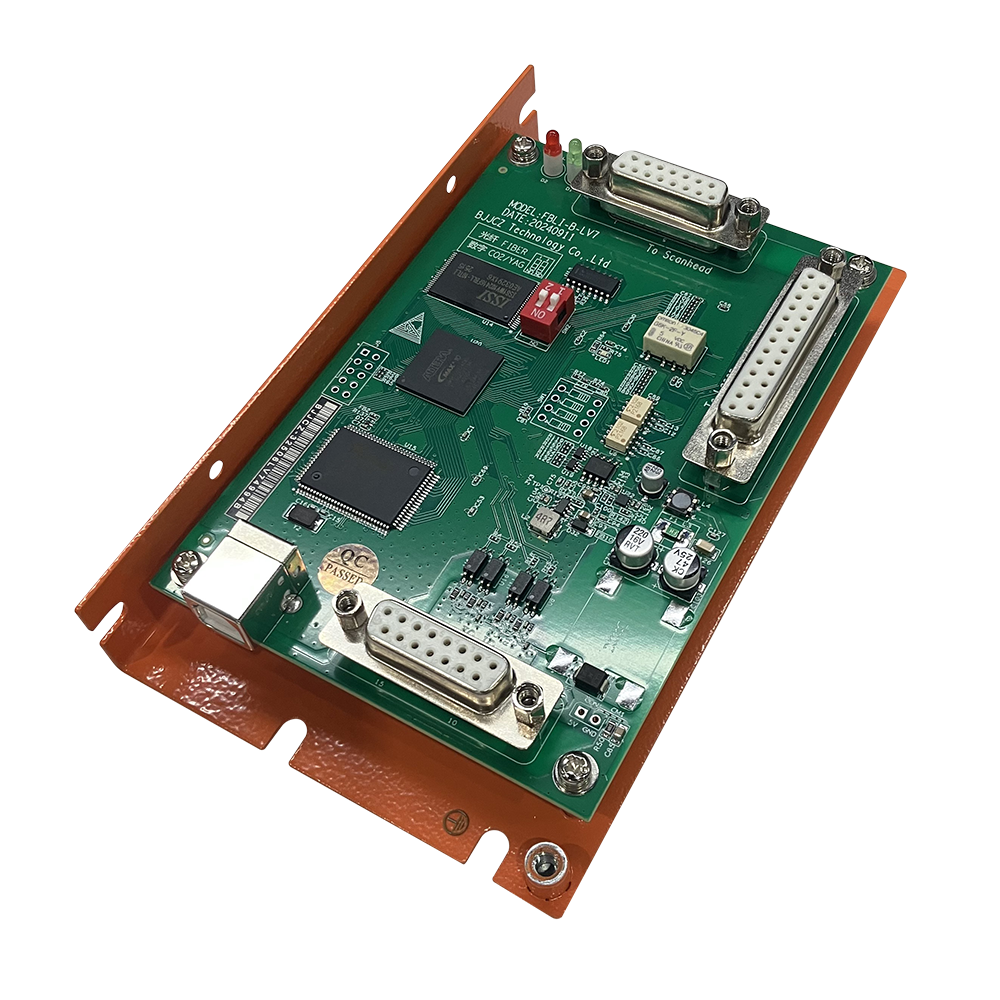
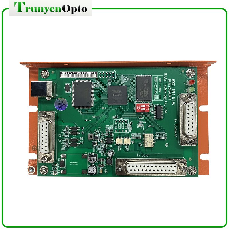
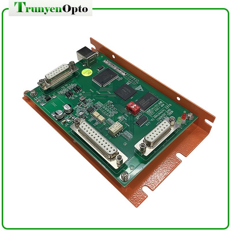
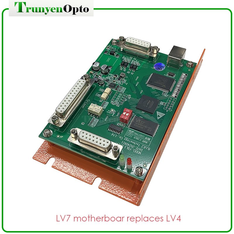
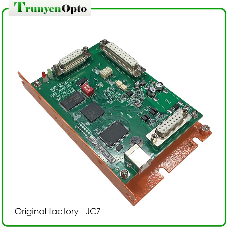
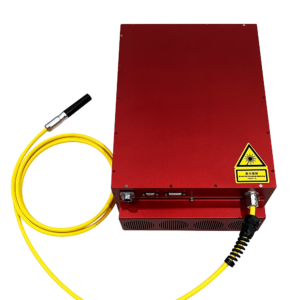
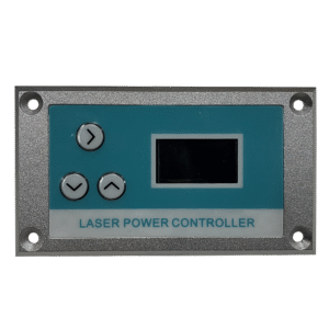
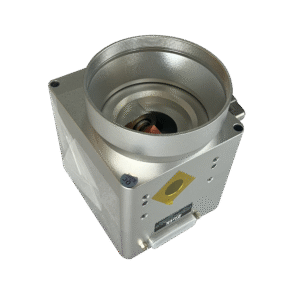
The DB25 socket controls laser output. It is directly connected to the pulsed fiber laser through a 25-pin cable.
The galvo control signal is a digital signal that can be directly connected to a common digital galvo.
In fiber laser mode, there are 3 universal input digital signals (TTL compatible): GIN4, GIN14, and GIN15. Among them, IN0~IN3 are designated as laser status input signals, which are introduced through the J3 socket (LaserST0~LaserST3).
In digital CO2/YAG laser mode, there are 4 universal input digital signals (TTL compatible): IN0, GIN4, GIN14, and GIN15.
Two universal output digital signals (TTL compatible) in fiber laser mode: Out4 and Out5.
Two universal output digital signals (TTL compatible) in digital mode: Out4 and Out5.
START (cache content duplicate marking) signal: used for situations where the marking content is the same and high-speed marking is required. If the marked content contains variable text, or if there is too much marked content to save fully on the board, connect it to a universal input signal.
Compatible with USB 2.0.
By selecting the DIP switch, the board can operate in fiber mode or CO2/YAG mode.
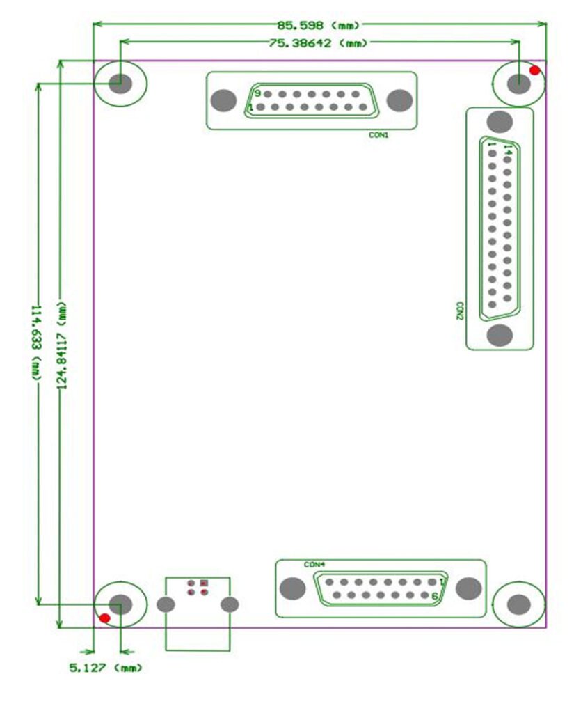
2 Interface Description
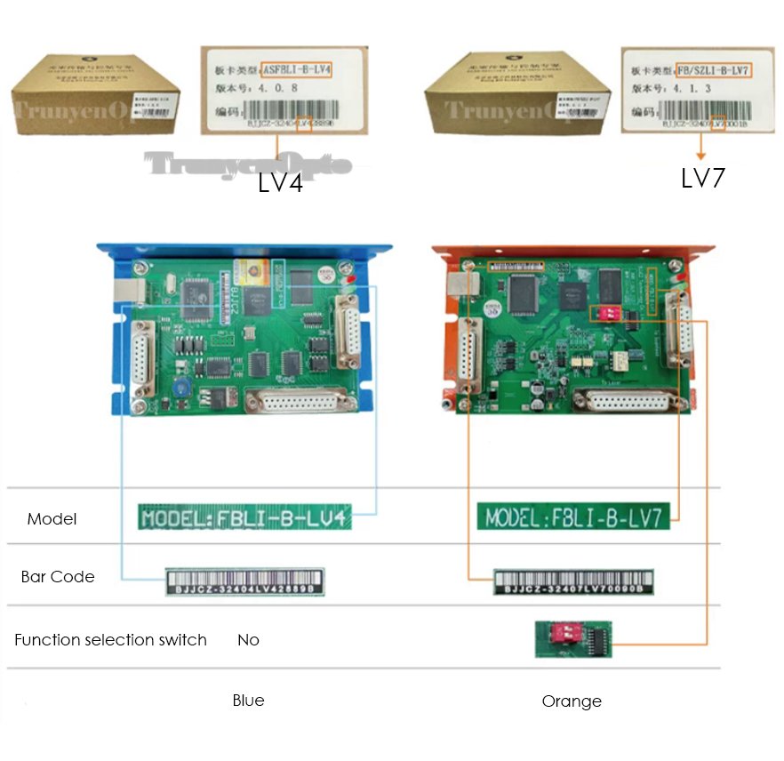
3 Differences between JCZ LV4 and JCZ LV7 for laser marking system